Motorheads are always in search of ways for more power or less
weight. When it comes to removing weight from your Mustang, taking
it off the front end of the car is preferable to removing it from
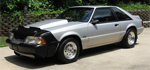
elsewhere. With this in mind, I decided to remove some weight
from the front of my 93 LX coupe using a tubular front-end
system and switching to manual steering. Of course there were
some "snags" encountered along the way but if you follow along
with my install, hopefully I can save you some aggravation.
With the popularity of the Fox Mustang being at an all time high,
 there are many front suspension systems available. But which one
should you choose for your car? My decision was based on the
purpose of the car, in my case a street/strip fun car, and as
there are many front suspension systems available. But which one
should you choose for your car? My decision was based on the
purpose of the car, in my case a street/strip fun car, and as
 such I looked at a few different companies before settling on
the kit from
Unlimited Performance. You should be aware that
not all tubular K-members are alike. Some move the control arm
mounting points forward as compared to stock which might
benefit the road racer. Others move the engine mounting points
toward the rear for redistribution of weight while others
such I looked at a few different companies before settling on
the kit from
Unlimited Performance. You should be aware that
not all tubular K-members are alike. Some move the control arm
mounting points forward as compared to stock which might
benefit the road racer. Others move the engine mounting points
toward the rear for redistribution of weight while others
 have no provisions for motor mounts all together as they
are intended to be used with a motor plate for securing
the engine. And finally, some K-members do not have
provisions for stock style front springs since they are to
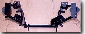
be used only with coilovers. The Unlimited Performance
K-member retains all stock mounting locations for springs,
steering rack, motor mounts and control arms. It can also
be used with coilovers as well as factory or aftermarket
control arms. This K-member is constructed of chromemoly
tubing which makes it even lighter than comparable units
have no provisions for motor mounts all together as they
are intended to be used with a motor plate for securing
the engine. And finally, some K-members do not have
provisions for stock style front springs since they are to
be used only with coilovers. The Unlimited Performance
K-member retains all stock mounting locations for springs,
steering rack, motor mounts and control arms. It can also
be used with coilovers as well as factory or aftermarket
control arms. This K-member is constructed of chromemoly
tubing which makes it even lighter than comparable units
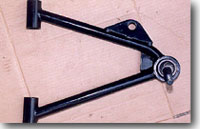
 made of mild steel. The finish is a nice black powder
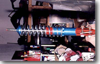
coating for durability. The tubular control arms are also
of chromemoly construction with the same gloss black powder
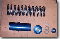
coated finish. The Unlimited Performance coilovers
feature aluminum sleeves and adjustable mounts in a blue
anodized finish, springs and a top mount with a
Torrington roller bearing. The supplied control arm bushings are urethane
and come with chromemoly bushing sleeves. Ride height is fully
adjustable by screwing in or out on the spring perch.
made of mild steel. The finish is a nice black powder
coating for durability. The tubular control arms are also
of chromemoly construction with the same gloss black powder
coated finish. The Unlimited Performance coilovers
feature aluminum sleeves and adjustable mounts in a blue
anodized finish, springs and a top mount with a
Torrington roller bearing. The supplied control arm bushings are urethane
and come with chromemoly bushing sleeves. Ride height is fully
adjustable by screwing in or out on the spring perch.
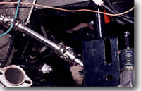
For the Steering components,
Flaming River's quick ratio manual
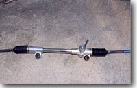 steering rack and solid steering shaft were selected. I also used
Flaming River's outer tie rod ends. Flaming River has different
solid steering shafts as well as tie rods depending on whether you
steering rack and solid steering shaft were selected. I also used
Flaming River's outer tie rod ends. Flaming River has different
solid steering shafts as well as tie rods depending on whether you
 are converting a power or manual rack car to begin with. The rack
I selected features 3.33 turns lock to lock and a 15:1 ratio. The
rack comes with new steering rack bushings; these would not work
with the Unlimited Performance K-member however. The K-member
are converting a power or manual rack car to begin with. The rack
I selected features 3.33 turns lock to lock and a 15:1 ratio. The
rack comes with new steering rack bushings; these would not work
with the Unlimited Performance K-member however. The K-member
 utilizes an older style Fox bushing which had to be obtained
locally. This style bushing does away with the inner metal sleeve
and slides onto the rack mount with one in behind and another in
front of the rack. The 93 Mustang stock hardware would also not
work and required a trip to the hardware store to secure a couple
grade 8, 1/2" coarse thread bolts of about 1" length and
corresponding washers. Due to the powder coated K-member a tap
was required to clean out the holes before the bolts to the
steering rack could go through.
utilizes an older style Fox bushing which had to be obtained
locally. This style bushing does away with the inner metal sleeve
and slides onto the rack mount with one in behind and another in
front of the rack. The 93 Mustang stock hardware would also not
work and required a trip to the hardware store to secure a couple
grade 8, 1/2" coarse thread bolts of about 1" length and
corresponding washers. Due to the powder coated K-member a tap
was required to clean out the holes before the bolts to the
steering rack could go through.
There were a few other items involved in this front-end makeover
in order to complete the installation. When such a system is
 installed it will be required that you use aftermarket
caster/camber plates in order to maintain front-end alignment.
Maximum Motorsports CC plates were used for this conversion. The
coilovers will work with stock style struts as well as
Koni or
Lakewood struts. The car used for the installation already has
Lakewood 70/30 front struts and these were retained. It is
important to note that these struts have a dust cover that is
spot welded on and must be removed before the coilover sleeves
and springs will go on the strut. Care must be exercised when
attempting to remove this dust cover, as the spot welds need to
be drilled out. The trick is to not go completely through the
welds with the drill bit for fear of drilling into the strut
installed it will be required that you use aftermarket
caster/camber plates in order to maintain front-end alignment.
Maximum Motorsports CC plates were used for this conversion. The
coilovers will work with stock style struts as well as
Koni or
Lakewood struts. The car used for the installation already has
Lakewood 70/30 front struts and these were retained. It is
important to note that these struts have a dust cover that is
spot welded on and must be removed before the coilover sleeves
and springs will go on the strut. Care must be exercised when
attempting to remove this dust cover, as the spot welds need to
be drilled out. The trick is to not go completely through the
welds with the drill bit for fear of drilling into the strut
 itself thereby rendering it useless. I did this during the
install and heard an awful "Pssst" sound as I penetrated through
the strut. Another trip to the store was required to buy another
strut, so be careful when doing this. A tip that may help is to
drill part way through the spot weld then use a drift punch and
hammer to knock the dust cover loose as you hold the strut in a
bench vice. I was able to remove the dust covers without any
damage to the strut using this method. This was followed by
blowing the top of the strut off with compressed air in order to
remove any metal fillings that may have collected around the
strut shaft.
itself thereby rendering it useless. I did this during the
install and heard an awful "Pssst" sound as I penetrated through
the strut. Another trip to the store was required to buy another
strut, so be careful when doing this. A tip that may help is to
drill part way through the spot weld then use a drift punch and
hammer to knock the dust cover loose as you hold the strut in a
bench vice. I was able to remove the dust covers without any
damage to the strut using this method. This was followed by
blowing the top of the strut off with compressed air in order to
remove any metal fillings that may have collected around the
strut shaft.
Before proceeding with the new parts I elected to purchase new
control arm bolts and nuts from the local
Ford dealership. These
carry part number N804591-S100 and N800237-S427 respectively.
After obtaining these bolts it turns out they would not slide
through the control arm bushing sleeves as supplied by Unlimited
Performance. The inside diameter of these sleeves measured .008"
undersize according to my dial calipers. A phone call later to
Unlimited Performance Products verified that indeed they had sent
out a few undersize sleeves by mistake and new sleeves were on
the way. These new sleeves were correctly sized and the bolts
slid right through. The ends were a bit rough and a little
filling was necessary to clean them up. The dust boots for the
greasable ball joints were then installed on the tubular control
arms, as were the zerk fittings. This car had previously been
changed over to 5-lug front rotors using the Motorsport M2300-C
kit. While they were off the car during this front suspension
redo, it was thought that the addition of NHRA legal long studs
would be a good idea. This brings up yet another minor problem.
The Ford studs are 1/2" and feature a .560" knurl while all
aftermarket long studs in this size knurl are 7/16". This makes
it necessary to open up the holes in the rotor to fit the more
common .615" knurl stud. For this purpose a set of Moroso 3" long
studs of the correct 1/2" diameter and proper .615" knurl were
utilized. The rotor holes were opened up by a local machine shop
using a self-centering bit. Also of note is the fact that the
holes are not opened all the way to .615" because an interference
fit is needed. Getting the holes opened up this way ensures that
the holes are centered and eliminates possible wheel balance
problems which can happen if you enlarge the holes by hand.
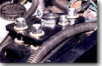
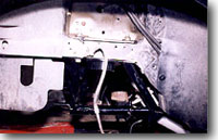
It's now time to get greasy! The engine in my car was removed and
this made the job a bit easier. If you still have your engine in
 the car it will be necessary to lift the motor and its mounts
slightly in order to remove the stock K-member. Before proceeding
with the K-member removal, you will need to remove the stock
struts, spindles, brakes, caster/camber plates, steering rack and
control arms. Take care to avoid injury when removing the front
springs! They are under tremendous pressure and must be handled
carefully and safely. I use a floor jack under the control arm
and with the top strut mount loose slowly lower the floor jack.
This allows the spring to extend to the maximum and then I use a
pry bar to pop it out while standing away from the wheel well
area. Disconnect the tie rods and remove the spindles and don't
forget the sway bar as well. Now you can remove the K-member
bolts (4 per side) and drop the K-member using a floor jack.
Again, be careful, as this piece is heavy. I left my stock
control arms attached to the K-member since I was switching to
the aftermarket units. Using a bathroom scale I found that my
the car it will be necessary to lift the motor and its mounts
slightly in order to remove the stock K-member. Before proceeding
with the K-member removal, you will need to remove the stock
struts, spindles, brakes, caster/camber plates, steering rack and
control arms. Take care to avoid injury when removing the front
springs! They are under tremendous pressure and must be handled
carefully and safely. I use a floor jack under the control arm
and with the top strut mount loose slowly lower the floor jack.
This allows the spring to extend to the maximum and then I use a
pry bar to pop it out while standing away from the wheel well
area. Disconnect the tie rods and remove the spindles and don't
forget the sway bar as well. Now you can remove the K-member
bolts (4 per side) and drop the K-member using a floor jack.
Again, be careful, as this piece is heavy. I left my stock
control arms attached to the K-member since I was switching to
the aftermarket units. Using a bathroom scale I found that my
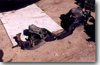 stock stamped steel K-member with factory control arms weighed
79.5 lb. The previously removed power steering rack, pump, and
lines with fluid accounted for another 38 lb. The Eibach drag
launch front springs I removed weighed 10 lb. each. By
comparison, the Unlimited Performance tubular front end and
Flaming River manual rack weighed 29 lb for the K-member, 6 lb
for each control arm, 6 lb for each coilover unit (without strut)
and 11 lb for the manual steering rack. This represents weight
savings of 73.5 lb (stock components add up to 137.5, aftermarket
64 lb). Incidentally, the stock front sway bar weighed in at 24
lb and will be replaced by a lightweight
Steeda unit at 11 lb,
which brings my total weight savings to 86.5 lb.
stock stamped steel K-member with factory control arms weighed
79.5 lb. The previously removed power steering rack, pump, and
lines with fluid accounted for another 38 lb. The Eibach drag
launch front springs I removed weighed 10 lb. each. By
comparison, the Unlimited Performance tubular front end and
Flaming River manual rack weighed 29 lb for the K-member, 6 lb
for each control arm, 6 lb for each coilover unit (without strut)
and 11 lb for the manual steering rack. This represents weight
savings of 73.5 lb (stock components add up to 137.5, aftermarket
64 lb). Incidentally, the stock front sway bar weighed in at 24
lb and will be replaced by a lightweight
Steeda unit at 11 lb,
which brings my total weight savings to 86.5 lb.
Installation of the tubular K-member was fairly easy. It is so
 light that I was able to hold the K-member in place with one hand
as I installed the bolts with the other hand. At this time its
probably not a bad idea to go ahead and check the K-member
alignment using a couple of strings as described in the
"
Mustang Performance Handbook 2 : Chassis and Suspension Modifications for
Street, Drag and Road Racing Use."
by Mathis. This uses known chassis points as well as two K-member
mounting points to take cross measurements. The cross measurements
should be within 1/4". Next, the control arm bushings and sleeves
light that I was able to hold the K-member in place with one hand
as I installed the bolts with the other hand. At this time its
probably not a bad idea to go ahead and check the K-member
alignment using a couple of strings as described in the
"
Mustang Performance Handbook 2 : Chassis and Suspension Modifications for
Street, Drag and Road Racing Use."
by Mathis. This uses known chassis points as well as two K-member
mounting points to take cross measurements. The cross measurements
should be within 1/4". Next, the control arm bushings and sleeves
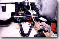 were installed into the tubular control arms using grease on the
bushings. The control arms took a bit of a struggle to get into
the K-member mounts but the bolts were eventually slid through
and everything stayed in place. I also recommend using a bit of
anti-seize compound on these fasteners as well as the K-member
bolts just in case you need to remove them in the future. The
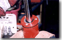
coilovers were then assembled on the strut but in order to fit
the top mount into the spring, another trip to the machine shop
were installed into the tubular control arms using grease on the
bushings. The control arms took a bit of a struggle to get into
the K-member mounts but the bolts were eventually slid through
and everything stayed in place. I also recommend using a bit of
anti-seize compound on these fasteners as well as the K-member
bolts just in case you need to remove them in the future. The
coilovers were then assembled on the strut but in order to fit
the top mount into the spring, another trip to the machine shop
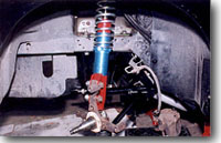 was required. A press was needed to seat the top mount into the
spring. The now assembled strut/coilover unit was placed on the
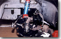
bench and attention directed to the caster/camber plates. The
Maximum Motorsports CC plates were then installed on the car and
the factory strut bumper stop eliminated. The spindle was
reattached to the control arm followed by the stut/coilover
assembly being loosely bolted into place. At this time it became
apparent that the coilover could interfere with the factory brake
line mount so this was moved out of the way and will later be
relocated.
was required. A press was needed to seat the top mount into the
spring. The now assembled strut/coilover unit was placed on the
bench and attention directed to the caster/camber plates. The
Maximum Motorsports CC plates were then installed on the car and
the factory strut bumper stop eliminated. The spindle was
reattached to the control arm followed by the stut/coilover
assembly being loosely bolted into place. At this time it became
apparent that the coilover could interfere with the factory brake
line mount so this was moved out of the way and will later be
relocated.
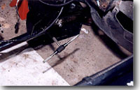
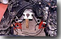
The Flaming River steering components were up next. When
installing the control arms make sure the threaded portion of
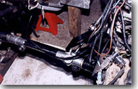 the bolt faces the inside (away from the steering rack). This
keeps the fasteners from rubbing on the steering rack boots as
you turn. The manual rack is then slid onto the mounts using
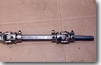
the rack bushings and fasteners as previously mentioned. The
solid steering shaft has a series of setscrews that require a
dimple to be placed prior to final assembly. This will be done
later after my motor is in the car so as to insure no rubbing
on any exhaust components. The u-joints on the solid steering
shaft must be assembled in phase as per the supplied diagram.
the bolt faces the inside (away from the steering rack). This
keeps the fasteners from rubbing on the steering rack boots as
you turn. The manual rack is then slid onto the mounts using
the rack bushings and fasteners as previously mentioned. The
solid steering shaft has a series of setscrews that require a
dimple to be placed prior to final assembly. This will be done
later after my motor is in the car so as to insure no rubbing
on any exhaust components. The u-joints on the solid steering
shaft must be assembled in phase as per the supplied diagram.
 Make sure you do not turn the steering wheel excessively in any
one direction while the steering shaft is out because it can
break the factory clock-spring mechanism causing the airbag light
to come on later. Once you have everything where you need it with
the solid steering shaft hooked up, turn the steering wheel from
center to full lock each side and count the turns while a friend
counts the turns on the steering shaft u-joint. You should have
fairly equal turns and if not then the u-joint needs to be turned
accordingly before re-installation on the steering rack.
Make sure you do not turn the steering wheel excessively in any
one direction while the steering shaft is out because it can
break the factory clock-spring mechanism causing the airbag light
to come on later. Once you have everything where you need it with
the solid steering shaft hooked up, turn the steering wheel from
center to full lock each side and count the turns while a friend
counts the turns on the steering shaft u-joint. You should have
fairly equal turns and if not then the u-joint needs to be turned
accordingly before re-installation on the steering rack.
The final steps involve installation of the rotors. Make sure the
 wheel bearings are packed with grease and torque the spindle nut
as per your shop manual. Don't forget a new cotter pin then
reinstall the caliper and relocate the brake hose mount to a
location that does not rub anywhere as you check full front
suspension travel and during turns. I used stainless steel
aliper bushing sleeves in place of the factory rubber bushings,
again don't forget the anti-size compound. The car will require a
wheel bearings are packed with grease and torque the spindle nut
as per your shop manual. Don't forget a new cotter pin then
reinstall the caliper and relocate the brake hose mount to a
location that does not rub anywhere as you check full front
suspension travel and during turns. I used stainless steel
aliper bushing sleeves in place of the factory rubber bushings,
again don't forget the anti-size compound. The car will require a
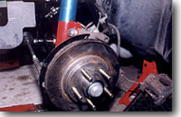 front-end alignment when done. The shaved front-end weight should
help improve both ET at the strip as well as handling. In
addition, there is more room for headers and enhanced oil pan
access. In my case the weight reduction should help offset the
added weight of the intended blower as well as the heavier than
stock cast iron TFS Street Heat heads. The car will get a newly
built blown 302 over the winter therefore driving impressions of
the new front end will have to wait a bit longer.
front-end alignment when done. The shaved front-end weight should
help improve both ET at the strip as well as handling. In
addition, there is more room for headers and enhanced oil pan
access. In my case the weight reduction should help offset the
added weight of the intended blower as well as the heavier than
stock cast iron TFS Street Heat heads. The car will get a newly
built blown 302 over the winter therefore driving impressions of
the new front end will have to wait a bit longer.
Always remember that there is no such thing as a "simple bolt-on".